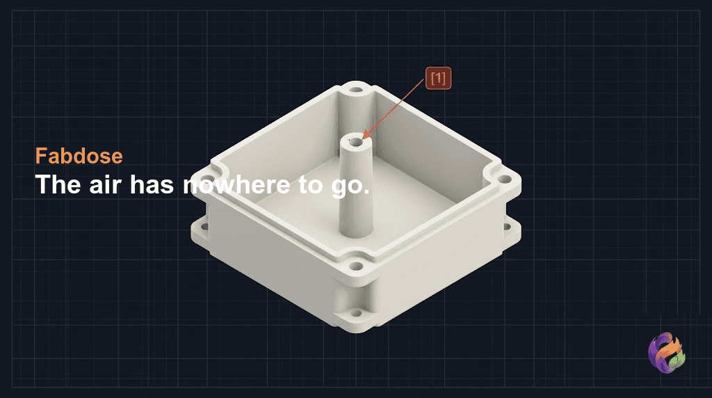
A 9mm screw boss with a 5.0mm bore down the middle. Take that boss from 15mm tall to 18mm and fabdose goes from saying nothing about it to flagging it at high severity, because the bore crosses a depth-to-opening ratio of 2.0 on the way up. Nothing else about the part changes, and nothing about how the boss looks on screen changes either.
The part below is a synthetic, illustrative model built for this post, not a real customer file. It is a 60 by 60 by 20mm wall-mount sensor housing in ABS with a 2.0mm nominal wall, carrying one 9.0mm screw boss standing off the interior floor. Two details about how it was built matter, and both cut against the demo rather than for it. The model has no draft anywhere, which keeps the bore a straight cylinder so the ratio is unambiguous, and which is also why fabdose returns 18 draft findings on it. And it is modeled open face up, the way it sits in the tool, because as you will see further down, that orientation is not a stylistic choice but a precondition for this particular check to fire at all.
Why does a deep, narrow blind hole trap air in the first place?
Because the melt seals the mouth of the hole before the hole is full, and the air underneath has no way out. As the shot advances, the flow front closes over the opening of the bore and turns it into a dead end. Everything injected after that compresses the air already inside. The compression happens far too fast for the heat to leave, so the temperature of that small pocket spikes hard. Published tooling references put the peak in the worst cases well above a thousand degrees Celsius, which is not a temperature any thermoplastic survives in contact.
Two failures come out of that, and which one you get depends on how much air is stuck. If the pocket is small, the superheated gas chars the plastic it touches and you get a dark, pitted, weakened patch at the bottom of the bore. If the pocket is large enough that its pressure rises to meet the injection pressure, the melt stops advancing entirely and the bottom of the hole simply never forms. Neither is visible in your CAD file, and neither is visible on the outside of the finished part, because the damage is at the bottom of a hole nobody is going to look into.
What did fabdose actually measure on the two versions of this housing?
The tall boss returned a depth-to-opening ratio of 2.40 against a 2.0 threshold, at high severity. Take 3mm off the boss and that finding is gone. Both runs used the same housing, the same ABS, and the same 2.0mm nominal wall. The screw bore stayed 5.0mm across in both, because a designer cannot change the screw.
| Tall boss | Shorter boss | |
|---|---|---|
| Boss top height | 18.0mm | 15.0mm |
| Blind bore diameter, as reported | 5.0mm | 5.0mm |
| Blind bore depth, as reported | 12.0mm | 9.0mm |
| Depth-to-opening ratio | 2.40, measured and reported by the check | 1.80, computed here from the two reported figures. A pocket that passes returns no finding, so there is no engine-reported ratio to quote |
| Fabdose threshold | 2.0 | 2.0 |
| Burn-mark finding | flagged, severity high | none |
| Other findings on the part | 18 | 18 |
| Base tooling | $1,500 | $1,500 |
The finding on the tall version comes back located rather than general. It names the pocket by feature reference, pocket_2, and gives the measured 2.40 against the required 2.0 with the 0.40 overshoot spelled out. The pocket record that reference points to is where the coordinate lives: x -18, y 0, z 6, which is the floor of the bore at the center of the boss. On a housing with a dozen bosses on it, the x and y are the part that tells you which one. The mechanism string fabdose returns is blunt: "Deep blind pocket compresses air at high pressure → diesel ignition of plastic at flow front." Its cited rule source is a mold venting requirement, ENG SPT UM section 11.6.8, rather than a number we picked.
One thing in that table deserves to be said out loud rather than left for you to find.
Look at the row counting the other findings. The shorter part is not clean. It still carries the same 18 draft findings and the same medium air-trap entry the tall one had. The burn-mark entry is the only thing that moved between the two runs, which is what makes this a usable comparison, but "the finding disappeared" is not the same sentence as "the part passed."
Is 2.4 a failure, and what about the 2:1 rule people quote?
No, and the ratio ladder you have probably seen quoted is answering a different question than fabdose's threshold is. These two get fused together constantly, and fusing them will lead you to the wrong conclusion here.
Fabdose's 2.0 comes from a venting requirement. It is about whether the gas at the bottom of the hole has a route out before the melt reaches it. The other ladder, the one that gets quoted as 2:1 for a standard unsupported core pin, 3:1 for larger unsupported pins, and as deep as 5:1 when the melt is gated to flow symmetrically around the pin or the pin sits in a slow-moving, low-pressure zone, is about something else entirely: the pin is supported at one end only, and the incoming melt pushes it sideways, so the ladder exists to stop the pin bending, breaking, or walking off position.
Those are separate failure modes that happen to share a ratio shape. A bore can sit comfortably inside the deflection ladder and still trap gas, and a well-vented bore can be deeper than the venting number without burning anything. So a 2.40 from fabdose does not mean "the literature says 3:1 is fine, therefore this is over-cautious." It means the geometry has left the range where nobody has to think about venting, and the answer now depends on things the part file does not contain: where the gate ends up, how symmetric the fill is around the pin, and whether the tool gets vented at that spot. Those are worth knowing before the steel is cut rather than after.
Does a taller boss show up in the tooling quote?
Not in the base tooling number. Both versions of this housing came back at the same $1,500 with no added line items. Boss height does not add a mold mechanism. There is no slide, no lifter, no extra action, so the complexity tier has nothing to price differently, unlike the tooling jump an undercut creates when it forces a slide core. If you are scanning a quote for red flags, this one is not in the tier.
The finding does carry a cost estimate of its own, and it points somewhere else. Fabdose attaches a 5 to 10 percent unit cost impact to this defect type, $200 to $800 of tooling for venting work, and 1 to 3 seconds of cycle time for vent maintenance. Be clear about what those numbers are: they are fabdose's built-in reference ranges for the defect type, not figures computed from your geometry the way the $1,500 is. What they describe is real work on the molder's side. Venting a deep core pin means splitting the insert so air escapes through the mating clearance, swapping in a porous sintered pin that lets gas through the steel itself, or grinding fine flats a few hundredths of a millimeter deep along an ejector pin at the base of the feature. Fabdose also classifies the expected shop response for this defect type as negotiate rather than accept, which is the engine's way of saying a shop is more likely to raise it with you than swallow it.
Compare that to the corner fillet nobody charges you for, where the cost of getting it wrong shows up in the field instead. Here the cost is real, priced, and lands on someone else's side of the quote, which is a different problem but not a smaller one.
What does fabdose not know about this hole?
Quite a lot, and the check is only useful if you know which parts of it are assumptions. Four are worth stating plainly.
It does not know whether the mold will be vented. Fabdose reads your part geometry and has no view of the tool, so it cannot see where the parting line inserts sit, where the ejector pins land, or whether your molder already plans a porous pin at that boss. Every blind pocket is therefore treated as unvented. That is conservative on purpose, and it is why a flag should be read as "this depends on venting" rather than "this will burn."
It does not measure the opening. The number reported as the opening is the narrow width of the pocket floor. On a straight-walled bore like the one in this teardown those are the same, which is part of why this part was built without draft. On a real drafted boss bore the floor is the narrow end, so the reported figure will come in under the true opening and the ratio will read conservative. Useful direction to err in, but you should know which end is being measured.
It needs the part oriented the way it sits in the tool. The check finds pockets that open along the pull direction and have a flat floor. A bore that opens sideways in the file, or a part imported on its side, will not be picked up at all. The same coarseness runs the other way too: on this housing the detector also returns the entire hollow interior as a pocket, 18.0mm deep with a 56.0mm opening, which passes easily but shows that "pocket" here means a geometric shape, not a feature it recognizes as a screw boss.
It assumes a gate. Fabdose does not read a gate location from your file. It places one at top dead center by default and sizes it from the nominal wall, so anything downstream of gate position in the report is running on that assumption rather than on your actual tool.
Beyond those: it does not simulate the gas compression, does not run a flow analysis, does not predict the temperature at the bottom of the bore, and does not check the pin deflection question the 2:1 ladder is actually about. What it does is find the pocket, measure it, and put a coordinate on it, which is the part that is genuinely hard to do by eye on a housing with a dozen bosses in it.
How do you check your own part before it goes out for a quote?
By measuring every blind pocket's depth against the narrow width of its floor, feature by feature, the same way you would check a draft angle or an undercut. This is exactly the kind of defect that survives a careful design review, because there is nothing to see. The boss looks correct in the model. The hole looks correct in the model. The ratio is the only thing that gives it away, and nobody computes a ratio while orbiting a part on screen. Trapped air is one of a short list of injection molding defects that a static CAD render cannot show you, and it belongs to the same family of located, measurable, face-level findings we walked through on a real open-source bracket.
Fabdose reads your STEP or STP file on your own computer, finds the blind pockets it can see, and reports each one's measured depth, the narrow width of its floor, the ratio between them, and where on the part it sits, before the file goes out for a quote.
Check your design with Fabdose
FAQ
What depth-to-diameter ratio is safe for a blind screw boss hole?
Two different limits get quoted as one. Fabdose uses 2.0, from a mold venting requirement, which is about whether trapped gas can escape. The separate ladder of 2:1, 3:1 for larger unsupported pins, and up to 5:1 with symmetric gating or a low-pressure zone, is about the core pin bending under flow pressure. A bore can clear the deflection ladder and still trap gas.
Why does a deep, narrow blind hole cause a burn mark or an unfilled bottom?
The melt front seals the opening before the hole is full, trapping air with nowhere to go. The rest of the shot compresses that pocket faster than the heat can escape, and the temperature spikes. The superheated gas chars the plastic at the bottom of the bore, and if the pocket pressure reaches injection pressure, the melt stops and the bottom never forms.
Does a too-tall boss change the tooling quote?
Not the base number. Both versions here priced at $1,500 with no added line items, because boss height adds no mold mechanism. The finding does carry fabdose's reference estimate for the defect type, 5 to 10 percent on unit cost and $200 to $800 of tooling for venting, and that work lands on the molder. Fabdose classifies the expected shop response as negotiate rather than accept.
Can fabdose tell whether my molder will vent that boss?
No. Fabdose reads your part, not your mold, so it treats every blind pocket as unvented. A flag means the geometry depends on venting fabdose cannot see, and that is a question for your molder before steel is cut.
What is the cheapest fix for a boss bore that is too deep?
Shortening the boss, when the assembly allows it. Here, dropping the boss top by 3mm took the bore from 12.0mm to 9.0mm and the finding disappeared, with no change to the screw and no change to base tooling. If the height cannot move, the remedies move into the mold: coring from two sides, a split insert, a porous sintered core pin, or ejector pin flats at the base of the feature.
Fabdose is a desktop tool for checking STEP and STP files against injection molding design rules. It finds blind pockets that open along the pull direction with a flat floor, measures depth against the narrow width of the pocket floor, and flags any ratio above the 2.0 venting threshold with its location on the part, before the file goes out for a quote. It does not simulate gas compression or melt flow, does not know how your mold will be vented, does not read a gate location from your file, and does not predict whether a given part will actually burn or short. Your CAD geometry is processed on your own computer; defect findings and descriptions are processed by AI. The part in this post is a synthetic, representative model built to demonstrate the mechanism, not a real customer file; the cost figures are fabdose's built-in estimates, not a shop quote.