If you are a product designer who has sent STEP files to a contract manufacturer, this situation will be familiar.
Your 3D model looks clean. Smooth surfaces, tight corners, solid walls. You zoom in, rotate it, check every angle. It looks exactly like what you want to make.
Then first samples arrive. There's a dimple on the cosmetic face. A visible seam line where two flow fronts met. A cracked corner that snapped under almost no load. A black burn mark at the edge of a recessed pocket.
None of those problems existed in your CAD file. This pattern — discovering manufacturing defects at first sample rather than at the design stage — is not an isolated event. It is the normal outcome of a workflow where the designer and the factory each look at a part through different instruments. The designer sees geometry. The factory sees physics. The two do not always agree.
The defects are not in your geometry. They're in what happens when hot liquid plastic enters a sealed steel cavity and solidifies. Here are four of the most common ones, why they're invisible at the design stage, and what they actually cost when you find them too late.
What "invisible in CAD" actually means
"Invisible in CAD" means that a defect has a definite physical cause — a cause that is fully determined by your design geometry — but that cause produces no visible signal inside modeling software.
A CAD model represents geometry in a static, perfect state. It does not simulate thermodynamics, polymer shrinkage, fluid dynamics, or air compression. Every surface looks solid because in the digital world, it is. The physics only appear when molten resin enters a real mold.
This gap between what looks correct in a model and what behaves correctly in a tool is the central challenge of DFM review. Understanding it before files go to a contract manufacturer for quoting is the difference between a clean first sample and a mold rework.
1. Sink marks — the dimple you can't see coming
What it is: A sink mark is a shallow depression or dimple on an external surface, caused by volumetric shrinkage as the part cools.
What causes it: Plastic cools from the outside in. When a section of the part is thick — a heavy boss, a solid rib base, a reinforced corner — the inner core stays molten longer than the outer skin. As the core finally solidifies and contracts, it pulls the already-hardened outer surface inward.
Why CAD doesn't show it: Your model renders a static, perfect surface. There is no simulation of heat transfer or material contraction. A 4mm wall next to a 1.5mm wall looks completely fine because in the digital space, both are just surfaces.
What it costs: Sink marks almost always appear on Class-A cosmetic faces — exactly where you least want them. By the time you have a defective sample in hand, the mold is already cut. Adding steel back to a machined tool to thin out a thick section is expensive and sometimes impossible. The fix is often a partial or complete tool redesign.
2. Weld lines — the seam that looks like a crack
What it is: A weld line (also called a meld line) is a visible seam on the part surface where two separate flow fronts of molten plastic met and failed to fully bond.
What causes it: Plastic flows around obstacles — holes for buttons, bosses, shutoffs — and splits into separate streams. When those streams reunite on the other side, if the melt has cooled enough that polymer chains can no longer entangle, the two fronts bond weakly or not at all. The result is a thin line on the surface and a structural weak point inside the wall.
Why CAD doesn't show it: Your part is modeled as a single, homogenous solid. CAD has no concept of fluid flow paths, multiple injection gates, or where converging streams of resin will inevitably collide. The hole in your design is just a hole — not a flow splitter that will create a bond line.
What it costs: Weld lines are both cosmetic and structural problems. The visible seam looks like a hairline crack. More critically, the part can snap along that line under ordinary use. The fix — repositioning injection gates or adding venting near the confluence point — requires pulling the mold and reworking the tooling. Depending on gate location, it may require adding or moving steel, which is rarely cheap.
3. Sharp internal corners — the stress concentration you designed in
What it is: A sharp 90-degree internal corner (zero or near-zero radius) creates a stress concentration point that can cause the part to crack or shatter under load or even during ejection from the mold.
What causes it: Plastic is highly notch-sensitive. At a sharp internal corner, polymer chains cannot orient smoothly during solidification — they are forced to change direction abruptly. The molded-in stresses concentrate at that point. Any applied force, impact, or even residual stress from cooling tends to propagate a crack exactly there.
Why CAD doesn't show it: Sharp corners are easy to model and often look intentional. Modern product aesthetics favor crisp, precise edges. In a digital environment there are no cooling stresses, no impact loads, and no material sensitivity to corner radii. A 0mm radius edge looks exactly as strong as a 1mm fillet because neither is physically loaded in the model.
What it costs: This is one of the most common causes of plastic part failure in consumer products — and one of the most avoidable. The fix in tooling requires welding metal back into the mold corner and re-machining a fillet. It is painstaking work. The lesson is always the same: add a minimum internal radius of 0.5–1x wall thickness at design time. It costs nothing in CAD. It costs significantly more in steel.
4. Air traps and burn marks — the physics of a sealed steel vault
What it is: An air trap occurs when plastic flowing into a mold cavity outpaces the air's ability to escape, compressing the trapped gas until it either burns the surrounding plastic or blocks fill entirely.
What causes it: A mold is a sealed steel enclosure. As plastic rushes in, air must escape through microscopic vents machined into the parting line, ejector pin gaps, and deliberately placed vent channels. If the part design creates a recessed pocket, a deep narrow rib, or a geometry where plastic flowing from multiple directions converges and seals off an area before the air can exit, the trapped gas compresses violently. This adiabatic compression — sometimes called the diesel effect — can raise local temperature high enough to char the resin.
Why CAD doesn't show it: Your model exists in open digital space. The negative space around your geometry is just empty air to the software. There is no concept that in production, that negative space will be solid steel, that air will need a physical escape path, and that certain geometries will seal off areas before air can evacuate.
What it costs: Parts arrive with black, charred, or flaking edges — or fail to fill completely (short shots). The fix requires opening the mold and machining new venting channels, repositioning ejector pins, or modifying the geometry to eliminate the trapped pocket. None of this is fast.
Why you usually don't hear about this until first samples
In a typical quoting workflow, a product designer sends a STEP file to a contract manufacturer. The factory calculates a price based on part volume, material type, and mold size. Most manufacturers will not provide detailed DFM feedback until after the order is placed and tooling payment is received.
The physics issues — sink, weld, air trap — often don't surface until the factory cuts steel and runs T0 or T1 test shots. At that point:
- A flaw caught at the design stage takes minutes to fix and costs nothing.
- A flaw caught in a first sample means pulling the tool from the press, sending it to the tool room, welding metal, and re-machining. That adds days to weeks and costs hundreds to thousands of dollars per change.
The access gap here is structural, not adversarial. Manufacturers quoting your part are not running mold flow simulations as part of that process — and in the industry's established workflow, the responsibility for design-level geometry checks sits with the designer, not the supplier. By the time the factory has the leverage to flag a problem, rework is expensive on both sides.
What you can do before sending the file
The practical answer is to run your own geometry check before the file leaves your desk. Not a simulation — that requires software licenses and expertise most product designers don't have access to — but a geometry analysis against known injection molding rules.
Check the obvious DFM flags before quoting:
- Minimum draft angle on all vertical faces (typically 1–3 degrees depending on surface finish)
- Undercut detection — features that would prevent the part from ejecting without side actions
- Wall thickness uniformity — large variations create differential cooling and sink risk
- Internal corner radii — zero-radius internal corners are a known failure point
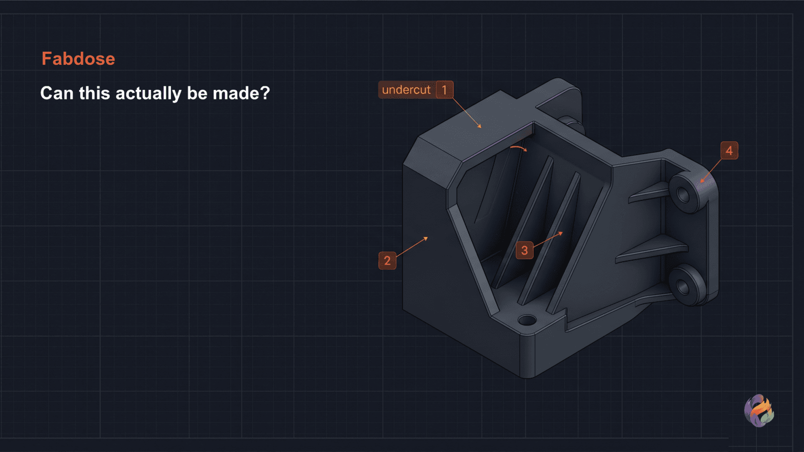
Fabdose analyzes STEP and STP files against injection molding geometry rules and locates draft violations, undercuts, internal corners with too small a radius, and deep blind pockets face by face, geometry-based checks that are deterministic from the design file alone, in about a minute. Pockets are judged on their depth-to-opening ratio, with venting assumed absent, since a STEP file does not show it. Your CAD files are processed locally on your computer; defect findings and descriptions are processed by AI. Sink marks, weld lines, and flow-front air traps (where the last plastic to fill lands off the parting line) require either simulation tools or an experienced DFM engineer to evaluate, and Fabdose does not replace that review.
The point is not to replace the manufacturer's DFM review. It's to show up to that conversation having already caught the problems that are plainly visible in the geometry — so the conversation is about the harder physics, not the basics.
FAQ
What is a weld line in injection molding?
A weld line is a seam that forms on a molded plastic part where two separate flow fronts of molten plastic meet inside the mold cavity. Because the plastic has cooled slightly by the time the fronts converge, the polymer chains do not fully entangle, leaving a visible line on the surface and a structural weak point in the wall. Weld lines are inherent to any geometry with holes, multiple gates, or complex flow paths.
Why do sink marks appear on injection molded parts?
Sink marks form because plastic shrinks as it cools, and thick sections cool more slowly than thin ones. When the outer skin of a part solidifies while the inner core is still molten, the contracting core pulls the surface inward, creating a shallow dimple. The root cause is uneven wall thickness — specifically, sections that are significantly thicker than the surrounding wall.
Can you see injection molding defects in a CAD file?
No. CAD software renders static, perfect geometry and does not simulate the thermodynamics or fluid dynamics of the injection molding process. Defects like sink marks, weld lines, air traps, and stress concentrations at sharp corners are entirely invisible in the model — they only emerge when hot plastic is injected into a real steel mold. This is why DFM review, which checks geometry against known manufacturing rules before tooling is cut, exists as a separate discipline from CAD design.
Fabdose is a desktop tool for checking STEP and STP files against injection molding design rules. Your CAD files are processed on your own computer. Defect findings and descriptions are processed by AI.