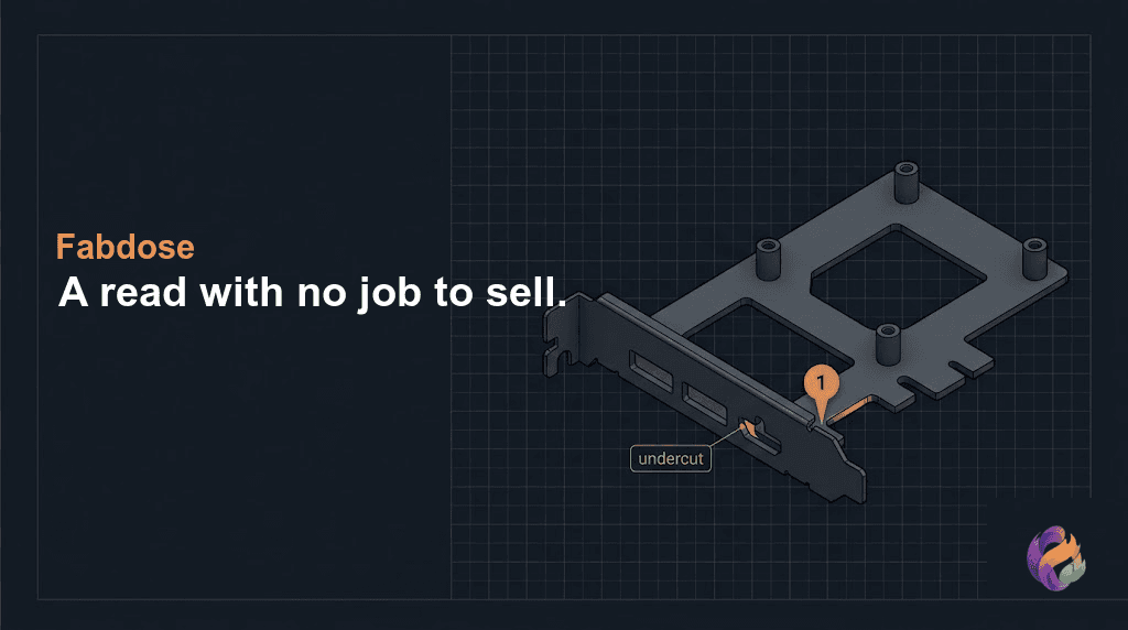
When you send a CAD part out for a quote, the first manufacturability opinion you get usually comes from the shop that wants the job. That opinion is useful, but it is not a neutral one: the party checking your file for free is the same party that quotes and profits from making it, so it has no structural reason to tell you the part could be redesigned cheaper — or sent to a different process entirely. Fabdose sits on the other side of that line. It does not quote jobs and does not sell manufacturing, so its read of your file has nothing to shade. To show what a neutral, pre-quote read actually looks like — and how concrete it can get — we pointed it at a real, finished-looking hardware part and read out, face by face, everything it flagged.
The part is not a synthetic test block. It is the PCIe bracket from the MIT ThunderScope open-source oscilloscope project — a genuine, functional mounting bracket exported to STEP. It looks completely finished. Before any shop had seen it, the neutral check located 44 issues on it: 18 undercuts and 26 faces with zero draft. Those numbers are not the headline on their own — they are the evidence that a read with no job to sell can still be this specific. Here is the full teardown.
Why not just upload the file to the vendor for a free check?
Because the free check and the quote come from the same desk. Most CNC and 3D-printing vendors will run your STEP file through an automated DFM check at no charge, and it is a genuinely useful service — you should use it. But it is worth being clear-eyed about the incentive behind it: the party checking your file is the party that gets paid to make it. A shop quoting the job has every reason to tell you the part is printable or machinable as drawn, and very little reason to point out that the same part could be re-drafted to cut its tooling cost, or that it belongs in a different process altogether. That is not a claim that vendors are dishonest. It is just the structure of who profits from which answer.
A read that does not quote the job and does not sell the manufacturing has no such structure behind it. Fabdose reads the file on your own computer, before you hand it to anyone, and it earns nothing from what you decide to make or where. That is the reason to run it first — not because it sees deeper than a shop's check, but because it has nothing riding on the answer. The rest of this post is what that neutral read produced on a real part, so you can judge for yourself how concrete "neutral" gets.
What part did we run, and why this one?
We ran the MIT ThunderScope PCIe bracket, a real open-source hardware component, not a demo shape built to fail.
We had three candidate STEP files on hand and ran all three through the same engine, the same command, in the same session. A snap-clip test part produced 3 issues. A demo enclosure produced 4. The ThunderScope bracket produced 44. We picked it precisely because it is the realistic case: a bracket with multiple standoffs and cutouts, the kind of part a product designer actually sends out for a quote, and the only one of the three that surfaced both located finding types — undercuts and draft — across a large enough sample to be worth reading in detail.
For the record, the run used ABS as the material and single-process injection molding mode. The material choice does not change the geometry findings; it only affects material-compatibility numbers. The geometry analysis itself finished in about two seconds. (In the desktop app, the written explanation of each defect is generated by AI and adds time on top of that — but the geometry work, the part that finds and locates the faces, is a couple of seconds.)
What did Fabdose find on it?
It located 44 geometry issues: 18 undercuts marked critical, and 26 faces below the minimum draft angle, marked medium.
Every one of those 44 is tied to a specific face on the model — not a general warning that "this part has undercuts," but a face ID, an angle, and a position in millimeters. That specificity is what makes a neutral read worth running first: it is not a vague "looks hard to mold" verdict you have to take on trust, it is a face you can open in your own CAD tool and check. The rest of this post is that data, straight from the run.
What are the 18 undercuts, and why do they matter?
An undercut is a feature that sits sideways to the direction the mold opens — a hook that wraps around the steel — so a standard two-part straight-pull mold cannot open without tearing the feature off the part. That condition is called a die-lock. To release an undercut, the moldmaker has to add a moving mechanism to the tool, such as a side-action slide or a lifter, that retracts before the part is ejected.
Fabdose located 18 of them on this bracket. Each row below is a real face from the run, with the angle its outward normal makes relative to the mold-pull direction (a face near 180 degrees is fully re-entrant — pointing straight back against the pull):
| Face ID | Angle (deg) | Position (x, y, z mm) |
|---|---|---|
| 27 | 180.0 | (-115.47, -0.31, 7.30) |
| 29 | 180.0 | (-2.72, -0.39, 8.09) |
| 30 | 176.3 | (-9.96, -0.39, 8.13) |
| 32 | 135.6 | (-11.03, -0.39, 3.65) |
| 33 | 180.0 | (-60.26, -0.39, 3.20) |
| 34 | 135.0 | (-110.72, -0.39, 5.25) |
| 38 | 135.0 | (-1.73, -0.39, 0.41) |
| 41 | 135.0 | (-6.35, -0.58, 6.70) |
| 45 | 180.0 | (-6.35, -4.79, 6.12) |
| 51 | 180.0 | (0.39, 5.08, 4.58) |
| 54 | 135.0 | (0.39, 10.74, 0.69) |
| 56 | 120.0 | (0.52, 11.46, 5.26) |
| 62 | 103.0 | (-0.18, 10.01, 6.81) |
| 63 | 120.0 | (0.52, 7.27, 10.61) |
| 64 | 96.5 | (0.78, 9.39, 11.79) |
| 66 | 167.0 | (0.10, 9.35, 10.58) |
| 68 | 103.0 | (0.58, 10.11, 11.30) |
| 73 | 135.0 | (-119.36, -0.01, 7.99) |
The engine's verbatim message for the first one reads: "Critical undercut, requires complete redesign or advanced mold technique detected at face 27 (angle: 180.0 degrees)."
Why does this matter in dollars and weeks? Because each of those 18 faces, if it survives to tooling, forces a moving mechanism into the mold. Fabdose's built-in cost model — which is a static estimate, not a factory quote — attaches a slide-core line item to every undercut it finds. Whatever the real number turns out to be, the direction is the same one every moldmaker will tell you: a side-action slide runs on the order of 50 to 80 hours of toolmaking, a lifter 100 to 200 hours, and an unscrewing core for threads 200 to 300 hours. Eighteen of those decisions are sitting in this bracket, and not one of them is visible in the CAD render.
Why are 26 faces flagged for zero draft?
Every one of the 26 draft findings is a vertical wall with exactly zero degrees of draft, measured against a 2-degree minimum. That is the single most common as-designed CAD default, and it is exactly what the check is built to catch.
Draft is the slight taper every wall needs in the mold-opening direction. When molten plastic cools it shrinks and grips the steel; a wall with no taper has to be dragged straight off the core under friction, which leaves scuff marks — drag marks — on every part in the production run, and in bad cases warps the part during ejection. Fabdose's rule set uses a 2.0-degree minimum for a smooth surface, and this bracket's walls come in at 0.0.
Here are 10 of the 26 flagged faces (the full set is in the run):
| Face ID | Current draft (deg) | Min required (deg) | Position (x, y, z mm) |
|---|---|---|---|
| 8 | 0.0 | 2.0 | (0.39, 11.43, 3.55) |
| 10 | 0.0 | 2.0 | (-58.03, -0.00, 12.29) |
| 14 | 0.0 | 2.0 | (-117.41, 0.22, 12.40) |
| 15 | 0.0 | 2.0 | (-120.05, 0.05, 12.40) |
| 18 | 0.0 | 2.0 | (0.79, 5.81, 10.58) |
| 21 | 0.0 | 2.0 | (-0.36, 0.36, 9.53) |
| 28 | 0.0 | 2.0 | (-2.13, -0.39, 4.42) |
| 31 | 0.0 | 2.0 | (-10.57, -0.39, 6.12) |
| 50 | 0.0 | 2.0 | (0.39, 7.24, 9.14) |
| 60 | 0.0 | 2.0 | (0.10, 11.44, 6.50) |
The engine's message for the first one: "Draft angle 0.0 degrees at face 8 is below minimum 2.0 degrees." This is not a trick part chosen to look bad. Modeling walls at exactly 90 degrees is what CAD tools make natural, and the draft pass is a step designers add later — or forget. That is the honest, ordinary pattern the check surfaced here.
What did the check deliberately NOT locate?
It did not locate weld lines or sink marks — and it should not, because those depend on melt flow and cooling, not on geometry alone. Air traps are a mixed case, covered below.
The same run did raise a weld-line risk flag, but it is worth being precise about what that means: the engine reported an estimated single location, not a specific face. Weld lines, tiger stripes, and warpage all showed up in the run as static risk flags — the tool has a rule library for them — but none of them carry a face ID, because they depend on melt flow, gate placement, cooling, and material, not on geometry alone. Air traps split in two. A deep blind pocket is geometry-only, so Fabdose now locates it face by face the same way it locates an undercut. The flag comes off the pocket's depth-to-opening ratio, with venting assumed absent, because whether the mold can vent that pocket is not in the STEP file. A flow-front air trap, where the last plastic to fill lands off the parting line, still depends on melt flow and stays a risk flag with no face ID. Those remaining flow-dependent risks are exactly what a manufacturer's DFM review or a flow simulation is for, and this check is not a substitute for that review.
That line — located versus flagged — is the honest boundary of what a face-by-face geometry check can do. A read with nothing to sell has no reason to overstate its own reach either, so it draws that line in plain sight: the 44 located findings are the ones worth acting on before a quote, and the flow-dependent risks are handed to a manufacturer's review, where they belong.
What does this teardown actually prove?
It proves that a read with no job to sell can still be this concrete: 44 located manufacturability problems on a part that looks completely finished, every one tied to a face, all of it produced before a single shop quoted the job. The capability is not the point in itself — it is the evidence that "neutral" does not have to mean "vague."
None of the 44 is exotic. Eighteen undercuts and twenty-six zero-draft walls are the bread-and-butter of injection molding DFM, and they are all deterministic from the STEP file alone. What is hard is not fixing them; it is seeing them, because a general once-over of the model tends to miss the inner wall of a standoff or the back face of a cutout — the faces that are not visible from the outside. A check that walks every face against the mold-pull direction does not miss them, and it hands you the exact face to open in your CAD tool.
Fabdose reads your STEP or STP file on your computer and locates, face by face, which walls are below the draft threshold and which features create undercuts — before the file ever reaches someone who profits from the answer. Your CAD geometry is processed locally on your own computer; the defect findings and their descriptions are processed by AI. It covers injection molding draft and undercut detection — the deterministic, geometry-only problems — and it does not simulate the flow-dependent defects that need a manufacturer's review. It does not quote your job or sell you the manufacturing, which is exactly why its read of the file has nothing to shade.
If you have a STEP file about to go out for a quote, the most useful moment to get a neutral read of it is before the quote — while every fix is still a file edit and no one yet has a stake in the answer.
Check your design with Fabdose
FAQ
Isn't the free DFM check from my manufacturer good enough?
It is useful, and you should use it — but it comes from the party that quotes and profits from making the part, so it has a structural reason to tell you the design is fine as drawn and little reason to suggest a cheaper redesign or a different process. That is not about vendors being dishonest; it is about who profits from which answer. A check that does not quote the job and does not sell the manufacturing has nothing riding on the answer. Fabdose runs on your own computer before you send the file anywhere and earns nothing from what you decide to make or where, so its read has nothing to shade. It is not deeper than a shop's check — it is neutral, which is a different and complementary thing.
How many manufacturability issues can a finished-looking CAD part have?
More than most designers expect. A real open-source PCIe bracket — a clean, functional CAD model — produced 44 located geometry issues when we ran it through an injection molding check: 18 undercuts that would stop the mold from opening on a straight pull, and 26 faces with zero draft that would drag against the steel during ejection. None of them are visible in a CAD render.
What is the difference between a located finding and a risk flag?
A located finding points to a specific face — with a face ID, an angle, and an X, Y, Z position — and says exactly where the problem is. A risk flag says a class of defect is likely somewhere on the part but does not pin it to a face. Undercuts and insufficient draft are geometry-only, so they can be located; flow-dependent defects like weld lines and sink marks need a manufacturer's DFM review or a flow simulation.
Why do undercuts make a mold more expensive?
Each undercut forces a moving mechanism into the tool — a side-action slide, a lifter, or an unscrewing core — that retracts before ejection, because a straight-pull mold cannot open around it otherwise. Those mechanisms add tooling hours, up-front cost, and maintenance. Every one of them can be avoided if the undercut is caught and redesigned while the part is still a CAD file.
What is the minimum draft angle for injection molding?
For a smooth surface the practical minimum is about 2 degrees per side (0.5 degrees is the absolute floor for polished surfaces, but 1 to 2 is the standard assumption). Textured surfaces need more — 3 degrees or higher. A wall modeled at exactly 90 degrees has zero draft and will drag against the mold steel during ejection.
Fabdose is a desktop tool for checking STEP and STP files against injection molding design rules. It locates draft violations and undercuts face by face, before the file goes out for a quote. It does not quote jobs or sell manufacturing. Your CAD geometry is processed on your own computer; defect findings and descriptions are processed by AI. The teardown above is a real, unmodified engine run against the MIT ThunderScope PCIe bracket; the cost figures cited are the tool's built-in static estimates, not factory quotes.