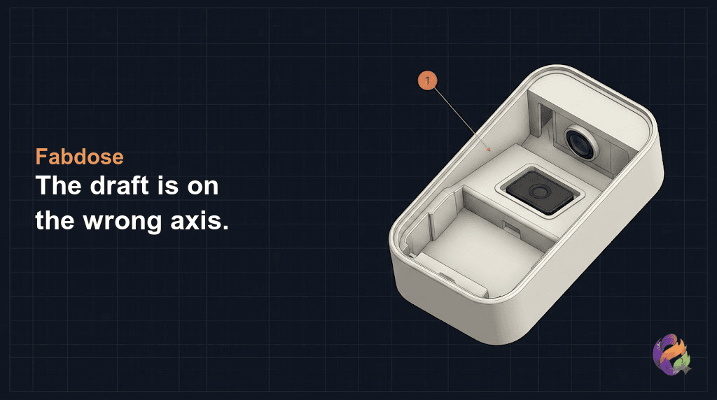
A camera module recess cut square into a 15 degree shelf. Add 3 degrees of draft to its walls and fabdose still reports two undercut faces, at 12.0 degrees instead of 15.0. The draft was not too small in some vague way. It missed by exactly 3 degrees, and the report says so, face by face, with a coordinate on each one.
The part below is a synthetic, illustrative model built for this post, not a real customer file. It is the rear shell of a wall-mount video doorbell, 60 by 100 by 24mm in ABS with a 2.0mm nominal wall, modelled open face up the way it sits in the tool. Inside it, an angled shelf aims the camera down at the doorstep, and the recess that seats the camera module is cut square into that shelf so the module sits flush. That is the ordinary way anyone would model it, and it is the reason two faces of the recess end up leaning back over the mold's pull direction.
Why is a wall that already has draft still an undercut?
Because draft only means something relative to the mold's pull direction, and a tilted face is not the pull direction. A straight-pull tool opens along one axis. Every wall has to taper in a way that lets the steel retreat along that axis, so the number that matters is the angle between the wall and the pull direction, not the angle between the wall and the surface it grows out of.
Write the tilt of the parent face as theta and the draft you applied as alpha. The wall on the uphill side of the feature ends up at alpha minus theta against the pull direction. Keep that positive and the part releases. Let it reach zero and the wall is vertical in the tool. Let it go negative and the wall is lying back over the pull axis, so a fixed core pin retreating along that axis is trapped underneath it and the part cannot come out without tearing. That is a die lock, and it is what the word undercut means here.
That subtraction is a way of reading the geometry, not a formula fabdose evaluates. The tool measures one resultant angle per face against the pull direction and reports that. The reason the number lands on alpha minus theta is that drafting about the tilted face rotates the wall in the same plane the face is already tilted in, which is exactly what happens when you pick that face as your neutral plane.
The trap is that CAD draft tools do not ask you for the pull direction. They ask you for a neutral plane. Pick the sloped shelf, which is the surface you are working on and the one the feature is referenced to, and you have applied taper in the wrong frame. The model rebuilds, the walls visibly taper, and nothing about the die lock has changed.
What did fabdose measure on the three versions of this shell?
Version one reports two undercut faces at 15.0 degrees. Adding 3 degrees of draft takes them to 12.0 degrees and leaves both in place. Only re-referencing the walls to the pull axis clears them. Same shell, same ABS, same 2.0mm nominal wall in all three runs.
| Square to the shelf | 3 degrees of draft about the shelf | Walls along the pull axis, 3 degrees of draft | |
|---|---|---|---|
| Undercut faces reported | 2 | 2 | 0 |
| Reported angle on each | 15.0 degrees | 12.0 degrees | none |
| Face IDs | 16 and 21 | 17 and 22 | none |
| Located at | (-18.88, 0, 15.07) and (-12.89, 0, 10.36) | (-18.95, 0, 15.10) and (-12.97, 0, 10.39) | none |
| What the report calls it | Severe undercut, requires slide core or redesign | Moderate undercut, consider redesign or lifter | none |
| Tooling tier | moderate | moderate | simple |
| Base tooling | $10,000 | $10,000 | $1,500 |
| Quoted lead time | 21 days | 21 days | 14 days |
| Draft findings on the part | 16 | 12 | 12 |
The two flagged faces are the uphill walls of the two recesses, the outer module seat and the lens well inside it. Both come back with a face id, a measured angle and an x, y, z position, which on a shell carrying several recesses is the part that tells you which one to open. The reported 15.0 is not a coincidence or a rounding: it is the shelf angle, because the walls have no draft of their own, so alpha minus theta is zero minus fifteen.
Then look at the last row, because it is the row that makes the middle column worth understanding. The 3 degrees was not wasted, and it did not land somewhere unrelated. It cleared four draft findings, taking the count from 16 to 12, and all four are the other two walls of each recess: the pair that runs parallel to the tilt rather than up and down it. On those, 3 degrees about the shelf normal arrives as 2.898 degrees against the pull direction, which is over the 2.0 degree minimum, so they pass. The same rebuild did nothing at all for the two uphill walls, and those are the ones that decide whether the tool needs a moving mechanism. A designer reading a shorter warning list after that rebuild could easily read it as progress on the wrong problem.
How much draft would have been enough?
More than 15 degrees, which is why the answer is not more draft. The condition is theta less than alpha, so a wall square to a 15 degree face needs more than 15 degrees of taper before it starts to release. Nobody designs that. Standard practice is 0.5 degrees as a floor and 1.0 degrees wherever the design allows it, with more on the core side than the cavity side because the plastic shrinks onto the core as it cools, and up to about 2 degrees on deep draws in stiff, low-shrink resins.
Put those two numbers next to each other and the practical rule falls out. Once a face is tilted more than roughly a degree away from the pull direction, a feature built square to it cannot be fixed by drafting it. The fix is to stop referencing the feature to the face and reference it to the pull direction instead.
That is what the third version does. The recess floor stays parallel to the 15 degree shelf, so the camera module still seats at 15 degrees and the product still looks down at the doorstep. Only the walls change: they run along the pull axis with 3 degrees of draft on them. A floor tilted 15 degrees and facing the opening is not an undercut, because it still has a positive component along the pull direction. Only walls that lean back over that direction are.
The round-boss version of this is the one you see asked about more often, where a screw boss stands square to a sloped face and someone suggests filleting the joint. A fillet reshapes the bottom of the transition and leaves the wall above it at the same tilt, so the steel still catches. The remedy there has the same shape as the one here: stand the boss on a flat pad set perpendicular to the pull direction, draft the boss normally against that axis, and let the fillet blend the pad into the slope.
What does the undercut cost if you leave it in?
Fabdose's base tooling figure moves from $1,500 to $10,000 between the clean file and the flagged ones, and the quoted lead time from 14 days to 21. Be precise about what that is. Those are tier lookups in fabdose's cost model, and the tier is keyed to how many undercuts the run found: none is simple, one or two is moderate. It is not a price computed for a specific slide on this specific geometry, and the way to read it is as a category change in the tool rather than a quote.
The published estimates for the mechanism are smaller and more specific than the tier jump. Classic design-for-assembly tooling data puts a plain side action slide at roughly 50 to 80 hours of extra toolmaking, and an internal lifter, which is what an undercut buried inside a housing usually needs, at roughly 100 to 200 hours because its retraction path has to be cut into the core and fitted by hand. At $40 to $45 an hour that is roughly $2,000 to $3,600 for one slide and roughly $4,000 to $9,000 for one lifter. A die casting reference states the floor more bluntly: even the simplest moving slide in a mold adds at least $1,000 of tool-making cost the moment it exists. So unlike the boss height that changed no cost line at all, this one is a real number on the quote, and it lands the same way a retention lip on an O-ring groove does.
Two costs after tooling are worth knowing about, because they are the ones nobody mentions when the decision is being made. A slide bar or a lifter rod cannot have cooling lines run through it the way the surrounding steel can, so that region of the tool runs hot and the cycle has to wait for it. And the sliding steel faces wear. Once there is play in the guides, the melt finds the gap and leaves flash along the edge of the part, which means periodic maintenance, hand trimming, and mold downtime for as long as the tool is in production.
What does fabdose not know about this?
Several things, and the check is only useful if you know which parts of it are assumptions.
It takes the pull direction from the file, not from you. The check evaluates every face against straight up in the coordinate system of the model, so the part has to sit in the file the way it sits in the tool. Import the same shell on its side and the entire list changes, which is a real answer with a real caveat attached rather than a fixed property of your geometry.
It reads one normal per face. On flat faces, which is all four walls of both recesses in this teardown, that is exact. On a single wrapped cylindrical face, such as a round boss standing on the same slope, one point of the circumference is sampled rather than the whole way around, so a tilted round boss is not guaranteed to be picked up. That is the case to check by hand with the theta and alpha comparison above rather than to assume the tool will catch.
The test is a sign test, not a tolerance. A face is called an undercut once it leans back past about half a degree, and everything past that is graded by angle rather than measured against a design limit. It tells you which faces are die-locked, not how much force it would take to strip the part off, and it does not simulate ejection at all.
It assumes where the mold splits. The one place it does form an opinion about the tool is the parting surface: it treats the flat bottom of the part as the parting line and exempts that face from both checks. It has no way to know whether your molder plans a stepped or offset parting surface instead, whether a lifter is already budgeted for that recess, or whether the feature could be shut off against the opposite half of the tool.
And the demo shell has an obvious flattering assumption worth stating. The angled shelf is modelled as a solid block rather than cored out under the module, which is why every one of the three runs also returns a wall-thickness finding of 11 to 13mm against a 3.56mm limit for ABS, and a cooling time between five and seven minutes. That number does not fall with the redesign. It rises, from just over five minutes on the first two versions to just under seven on the third, because the third version's recess floor leaves more material under it. So the honest summary of the third run is narrow: both undercut findings are gone and the tooling tier drops, while fabdose's overall readiness badge stays at Design Revision Required in all three versions, held there by the cycle time of an un-cored shelf. The third version also still carries 12 draft findings of its own.
How do you check your own part before it goes out for a quote?
By comparing the tilt of every face you have built a feature on against the draft you gave that feature, one at a time, in the pull direction of the tool. This is the kind of thing that survives a careful design review, because the model looks right. The recess is square to its shelf, which is what you intended. The walls taper, which is what you asked for. The number that gives it away is a subtraction nobody performs while orbiting a part on screen, and it is the same class of located, measurable, face-level finding we walked through on a real open-source bracket. If the terms here are new, the definitions of draft and undercut are worth reading first, and there is a separate list of the standard redesigns for the cases where the feature genuinely cannot be re-referenced.
Fabdose reads your STEP or STP file on your own computer, checks every face against the pull direction, and reports each undercut face with its measured angle and its position on the part, before the file goes out for a quote.
Check your design with Fabdose
FAQ
How much draft does a wall on an angled face need?
More than the tilt of the face it sits on. With a face tilted theta and a draft of alpha, the wall sits at alpha minus theta against the pull direction, and that has to stay positive. A wall on a 15 degree shelf would need more than 15 degrees of draft, which nobody designs. Since standard draft is 0.5 to 1.0 degrees, any feature square to a face tilted more than about a degree has to be re-referenced to the pull direction instead.
Why is a wall that already has draft still flagged as an undercut?
Because CAD draft tools apply taper relative to a neutral plane you choose, and picking the tilted face puts the taper in the wrong reference frame. Here, 3 degrees applied about a 15 degree shelf normal moved the reported angle from 15.0 to 12.0 on the same two faces. The finding shrank, it did not clear, and the tooling tier did not move.
Does a fillet at the base of the feature remove the undercut?
No. A fillet reshapes the bottom of the joint and leaves the wall above it at the same tilt, which is the wall the steel catches on. That is also why filleting the joint of a round boss standing square to a sloped face does not rescue it.
What does an undercut like this do to the tooling quote?
Fabdose's base tooling figure went from $10,000 to $1,500 and the quoted lead time from 21 days to 14 once both findings were designed out. Those are tier lookups keyed to the undercut count rather than a computed slide price. Published estimates for the mechanism are 50 to 80 toolmaking hours for a side action slide and 100 to 200 for an internal lifter, which at $40 to $45 an hour is roughly $2,000 to $3,600 for a slide and $4,000 to $9,000 for a lifter.
Can the module still sit at an angle after the fix?
Yes. A floor tilted 15 degrees and facing the opening still has a positive component along the pull direction, so it is not an undercut. Only walls leaning back over that direction are. The third version keeps the recess floor parallel to the shelf and the module still seats at 15 degrees, while the walls run along the pull axis with 3 degrees of draft.
Fabdose is a desktop tool for checking STEP and STP files against injection molding design rules. It evaluates each face against the mold's pull direction, taken as straight up in the file's own coordinate system, and reports every face that leans back over that direction with its measured angle and its position on the part. It reads one normal per face, does not simulate ejection, has no view of how your mold will be built, and its tooling figures are tier lookups from a cost model rather than a shop quote. Your CAD geometry is processed on your own computer; defect findings and descriptions are processed by AI. The part in this post is a synthetic, representative model built to demonstrate the mechanism, not a real customer file.