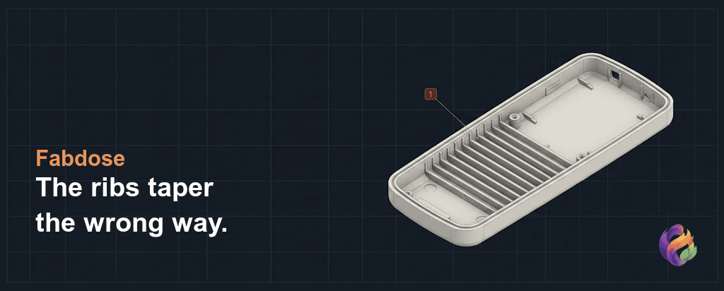
Five ribs across the floor of a remote-control shell. Draft them 2.0 degrees and the rib findings go to zero. Draft them 2.0 degrees the other way and the same tool returns 40 undercut faces, and the base mold cost in the cost summary goes from $1,500 to $50,000. Nothing about the outside of the part changed in either run.
Rib draft usually gets treated as a rounding error. The rib here is 1.4mm thick and 8mm tall, so two degrees on it is a change of about 0.28mm per side over the rib's full height. The sign of those two degrees is what moves the tooling tier.
The part below is a synthetic, representative model built for this post, not a real customer file. It is the lower shell of a handheld remote, 150 by 45 by 12mm in ABS with a 2.4mm nominal wall, modelled open face up the way it sits in the tool. The outer walls carry 2.5 degrees of draft, the cavity walls carry 2.5 degrees the other way so the core can withdraw, and five transverse ribs stand on the inner floor: 1.4mm thick at the root, 8.0mm tall, spanning 34mm across the width. Only the taper on those rib flanks changes between the four runs. Neither of the two runs in the opening sentence is issue-free overall, because the demo part carries a wall thickness problem that survives all four. That is covered at the end rather than buried.
Which way should an interior rib taper?
Thickest at the floor, thinnest at the top. The inside of an open-topped box is formed by a male core that projects up from the B-side of the tool, and that core has to withdraw straight back down out of the box. Every rib standing on the floor sits inside the core's exit path, so the rib has to narrow in the direction the core leaves.
The same fact reads differently depending on which side of the steel you look from, and that is where the mistake lives. Said about the plastic, the rib narrows going up. Said about the tool, the slot between two ribs is a pocket in the core, and a pocket has to open out toward the top so the steel between the ribs can clear. Both sentences describe one geometry. What makes it easy to get backwards is that the exterior walls of the same part also narrow going up, so a designer working outside-in gets used to a taper that closes toward the opening, while the interior hollow does the opposite and widens toward the opening. Apply the outside habit to an inside feature and you produce a mechanical undercut that seizes the part onto the core.
In practice the flip happens in one click. A CAD draft tool asks for a neutral plane and a direction. Pick the rib's top face as the neutral plane instead of the floor it grows from, keep the same direction you used on the outer walls, and the rib narrows downward. On screen the rib still looks tapered, because it is. If the terms here are new, the definitions of draft and undercut are worth reading first.
What does the report say when the taper is flipped?
The rib flanks stop being draft findings and become undercuts, one face at a time, each with a coordinate on it. All four runs went through the same command:
python cli.py analyze <part>.step ABS --process injection_molding --wall-thickness 2.4
Take one face and follow it across the runs. Face 16 is the long outward-facing flank of the leftmost rib, about 270 square mm, sitting at roughly x = -51, y = 0, z = 6.4 in the file's own coordinates.
| Run | Rib flanks | Face 16 angle | Face 16 finding |
|---|---|---|---|
| A | vertical, no draft | 0.0 | insufficient draft, below the 2.0 minimum |
| D | narrowing upward, 1.0 degree | 1.0 | insufficient draft, below the 2.0 minimum |
| C | narrowing upward, 2.0 degrees | 2.0 | clear |
| B | narrowing downward, 2.0 degrees | -2.0 | undercut |
The angle column is the per-face draft angle from the engine's geometry output, which carries a sign. The finding column is what the rule engine emits for that face, and an undercut's angle is reported there as a positive magnitude. That distinction matters in a moment.
Run A returns 20 findings, reading Draft angle 0.0° at face 15 is below minimum 2.0° and on through face 34. Those 20 are the four vertical faces of each of the five ribs: two long flanks at 271.9 square mm and two ends at 11.2 square mm. The rib top faces are not among them, because a face whose normal points straight up the pull direction scores 90 degrees and clears the minimum.
Run B returns zero draft findings and 40 undercut findings, every one of them reading Minor undercut, may not require action detected at face 15 (angle: 2.0°), with the face numbers running from 15 to 59 and skipping the five rib tops.
The location arrives alongside the message rather than inside it. Face 15 in run A is listed at x = -52.0, y = -16.995, z = 6.4 with a measured draft of 0.0 against a 2.0 minimum. The same face in run B is listed at x = -52.0, y = -17.135, z = 6.4 as an undercut. That is what turns "this part has undercuts" into "this rib, this flank, this end of it."
Why do five reversed ribs produce 40 findings?
Because each reversed rib splits into 8 flagged faces, not 4. Grouped by rib, run B puts 8 undercut faces on each of the 5 ribs: the 2 long flanks at 272.1 square mm, the 2 ends at 11.2, and 4 corner slivers at 1.8 square mm each. Those slivers exist only because a taper that widens as it rises splits each rib corner into an extra 45 degree facet when the solid is built. They are the same four corners of the same rib, subdivided.
Read it as 5 reversed ribs showing up as 20 substantive faces plus 20 corner fragments. The next section is about the count, so the count needs to mean something before you use it.
Why does "may not require action" still move the tooling tier?
Because severity is decided per face and the tooling tier is decided by the count. Two degrees of negative draft is a shallow catch, so each of the 40 findings lands in the lowest severity band and says so in plain words. The cost model does not read those words. It reads the undercut count, and it returns the complex tier once that count passes 4.
The consequence sits on the cost summary, not in the issue list:
| A no draft | D 1 degree up | C 2 degrees up | B 2 degrees down | |
|---|---|---|---|---|
| Insufficient-draft findings | 20 | 20 | 0 | 0 |
| Undercut findings | 0 | 0 | 0 | 40 |
| Complexity tier | simple | simple | simple | complex |
| Base mold cost | $1,500 | $1,500 | $1,500 | $50,000 |
| Tooling window | 2 to 4 weeks | 2 to 4 weeks | 2 to 4 weeks | 4 to 6 weeks |
| Lead time estimate | 19 days | 19 days | 19 days | 40 days |
| Itemised extra costs | none | none | none | none |
| Total issues | 27 | 27 | 7 | 47 |
$1,500 and $50,000 are tier lookups from Fabdose's cost model, keyed to the undercut count for the Korea region. They are not a computed price for a specific mechanism and they are not a shop quote. The itemised extras list is empty in all four runs, so nothing here claims a particular slide or lifter was priced.
The tier is also coarse by design. It has three steps for this region, $1,500, $10,000 and $50,000, and a count of 5 lands in the same place as a count of 40. For scale on what a mechanism costs inside the same model, the Korea cost data prices a slide core at $500 per unit and a lifter at $1,200 per unit. The step between tiers is far larger than any single mechanism the model knows how to price, which is the point: the tier is not counting mechanisms. Five reversed ribs in the middle of a core is not a geometry anyone solves with slides anyway. It is a geometry you fix in CAD, which is where the standard undercut redesigns end up when the feature is buried inside a closed volume.
How much draft does the rib actually need?
Published guidance starts at 0.5 degrees per side, with 1 to 2 degrees the standard recommendation. Fabdose's smooth-surface minimum is 2.0 degrees, which sits at the top of that range. That gap is why a correctly drafted rib can still come back flagged, and it is the first thing to check before you read the findings as errors.
Run D exists to show what that looks like. Its ribs are drafted correctly at 1.0 degree per side, a value most design guides list and most molders would pass without comment. The report still returns all 20 rib faces, each reading Draft angle 1.0° at face 15 is below minimum 2.0°. Nothing about the tier moved: still simple, still $1,500, still 19 days. The findings tell you where the faces are and what angle each carries. The threshold that decided to print them is the tool's.
Two adjustments go the other way and both make 2.0 look less conservative than it first appears. Deep draws want more, with one common rule of thumb adding about 1.0 degree for each of the first 50mm of depth and another adding 0.25 degrees for every additional inch beyond the first. Texture wants considerably more: the rule this site already documents adds 1.5 degrees for every 0.025mm of texture depth on top of a 1 degree base. Fabdose applies its 2.0 degree smooth-surface figure to every face regardless, because nothing in a STEP file says which surfaces will be textured.
What does the draft cost you at the rib tip?
On this 1.4mm rib, 8mm tall, 2.0 degrees per side takes the tip to 0.841mm, a 41 percent loss. The tip thickness is the base thickness minus twice the height times the tangent of the angle per side:
W_tip = W_base - 2 * H * tan(theta)
| Draft per side | Tip thickness | Rib top face area in the engine output |
|---|---|---|
| 0 degrees | 1.400mm | 47.59 square mm |
| 1.0 degree | 1.121mm | 37.78 square mm |
| 2.0 degrees | 0.841mm | 28.13 square mm |
The third column comes from the per-face geometry in the engine's own output, where every face carries its own area. The rib's top face is the tip, so its area falls from 47.59 to 28.13 square mm across those runs: the tip thickness times the tip length, both narrowed by the same taper. The desktop report summarises geometry rather than listing per-face areas, so that is the raw output rather than a screen you will see.
Two separate limits sit under the tip thickness, and neither is about how the part looks. A tip that runs too thin makes the melt hesitate as it turns up into the rib. Without shear heat it freezes off early and the rib fills short, which is the same flow-resistance problem a thin wide part runs into over its flow length. On the tool side, the gap beside the rib is a narrow slot machined into the core, cut with small and fragile end mills, and the steel blade left between two ribs has to be thick enough to carry heat away. Take the tip too thin and you get a blade that chatters when it is cut and runs hot when it is used.
So the design move on a tall rib is not simply more draft. Tip loss scales with height, so the same taper on a shorter rib costs proportionally less tip. Whether you can shorten the rib and keep the stiffness you needed is a structural question this check does not answer.
What does fabdose not know about these ribs?
It does not know how you will orient the part in the tool, whether any face will be textured, or where your parting line actually runs. The pull direction is taken as straight up in the file's own coordinate system, so a part modelled lying on its side gets a report answering a different question than the one you meant. The flat bottom face is treated as the parting surface by a bottom-face heuristic and exempted from both checks, which bakes in the assumption that the parting line runs along that flat bottom. A stepped or offset parting surface is outside what the tool can know.
It reads one normal per face. That is exact for the planar rib flanks here and arbitrary for a closed cylindrical face, so a round drafted boss is not guaranteed to be measured at its worst point. Check that case by hand.
It does not check rib proportions at all. The rib rule in the data files carries a maximum height ratio and a minimum spacing, but the rib check itself is not implemented, so nothing in these runs commented on the fact that an 8.0mm rib on a 1.4mm base is taller than the commonly quoted limit of roughly three times the base thickness. Every draft and undercut finding you see here is about the flank angle, never about whether the rib should be that tall.
Three things in these runs cut against a tidy story.
The demo shell is not cored out under its floor, so all four runs carry a wall thickness finding, with the measured figure landing between 12.93 and 16.95mm against a 3.56mm maximum for ABS. The runs did pass --wall-thickness 2.4, the actual nominal wall, but the thickness finding does not use that value. The geometry parser measures its own, and on a shape it reads as solid that measurement comes back as a whole-body figure, identical for the average, the maximum and the minimum in every run.
That finding is also why the readiness badge reads Design Revision Required on all four runs, including the corrected one. The same measurement drives the cooling time estimate, which is why the reversed version reports the shortest cooling time of the four at 418 seconds against 718.6 for the corrected one. That difference tracks the thickness sampler, not the quality of the design, and reading it as an argument for reversed ribs would be reading it backwards.
The corrected run still shows 7 total issues rather than zero: the one wall thickness finding plus six defect-risk entries. Only one of those six traces back to the thickness number. The rest come from separate checks on flow and venting that the rib change does not touch.
How do you catch a reversed rib before it goes out for a quote?
By checking every face against the direction the tool opens and reading which list each face lands in, not just the number printed on it. A reversed rib survives a design review. It is tapered, it is symmetric, it is the right size, and from outside the part nothing has changed. The angle printed on a reversed flank reads 2.0°, the same number the correct rib carries. What changed is the list above it: the same face, at the same coordinate, moved out of the insufficient-draft findings and into the undercut findings, and the undercut list is what the cost model counts.
That is the same class of located, face-level finding as the read on a real open-source bracket, and a close relative of what happens when draft is measured against the wrong reference face.
Fabdose reads your STEP or STP file on your own computer, checks every rib flank against the pull direction, and reports each face below the draft minimum or leaning back over that direction with its measured angle and its position on the part, before the file goes out for a quote. The free tier covers 5 analyses with no card.
Check your design with Fabdose
FAQ
Which way should an interior rib taper?
Thickest where it meets the floor, thinnest at its free top. The core forming the inside of the box pulls up and away from the floor, so a rib standing on that floor has to narrow in that direction. Said the other way round: the slot between two ribs is a pocket in the core steel, and a pocket has to open toward the top. A rib thinner at its base than at its tip cannot pass back through the slot that formed it, and the part locks onto the core.
How much draft does an interior rib need?
Published guidance puts the floor at 0.5 degrees per side, with 1 to 2 degrees the standard recommendation on polished surfaces and considerably more where the face will be textured. Fabdose is stricter than the floor: its smooth-surface minimum is 2.0 degrees, so a rib at 1.0 degree still returned 20 findings reading "Draft angle 1.0° at face 15 is below minimum 2.0°". That threshold belongs to the tool rather than to your molder. Read the angle it reports on each face and decide.
Each finding says "minor undercut, may not require action." Why does the price move?
Because severity is per face and the tier is per count. All 40 findings carried the lowest severity band, since 2.0 degrees of negative draft is a shallow catch. The cost model returns the complex tier once the undercut count passes 4, so 40 shallow findings and 5 deep ones land in the same place. Read the count as well as the severity word.
How do I fix a reversed rib without remodelling the part?
In most CAD tools it is one operation rather than a rebuild: delete the draft feature and re-apply it with the shell's inner floor as the neutral plane instead of the rib's top face, keeping the same pull direction. The rib geometry is otherwise unchanged. What makes this worth checking rather than assuming is that a reversed rib looks correct on screen.
Do the bosses and inner side walls on the same core need the same direction?
Yes. Every feature standing on the inner floor shares one exit path, so all of them have to clear the core in the same direction. A rib drafted the right way next to a boss drafted the wrong way still locks the part onto the core. In these runs only the rib flanks changed, which is why the outer walls at 2.5 degrees and the cavity walls at 2.5 degrees the other way stay clear in all four.
Fabdose is a desktop tool for checking STEP and STP files against injection molding design rules. It evaluates each face against the mold's pull direction, taken as straight up in the file's own coordinate system, reports every face below the draft minimum or leaning back over that direction with its measured angle and its position on the part, and applies one fixed smooth-surface threshold regardless of finish. It reads one normal per face, does not check rib proportions, does not simulate ejection, has no view of how your mold will be built, and its tooling figures are tier lookups from a cost model rather than a shop quote. Your CAD geometry is processed on your own computer; defect findings and descriptions are processed by AI. The part in this post is a synthetic, representative model built to demonstrate the mechanism, not a real customer file.