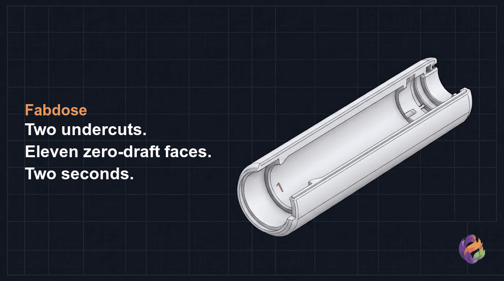
Two undercut faces. Eleven faces at zero draft. Three sections over the material maximum. One STEP file, one pass, a little over two seconds on my laptop, and every one of those findings named by its face number.
That is the narrow question about a part, closed. It is worth separating from the wide question, because of what three different people were each about to spend in order to get the narrow one answered.
Three unrelated threads, one week. One had a 3D printed product already selling and was about to buy an injection molding add-on for their CAD package, specifically so they could check draft angles themselves before committing to a mold. One had a finished industrial design and STEP files, and was hiring a product engineer specifically to de-risk manufacturability before manufacturing. One had STEP files and a BOM finished, and was shopping for a full-service manufacturing partner partly because that partner would catch fit and assembly problems before commit.
Different budgets, different stages, same underlying question: is there something in this geometry that is going to blow up when I commit to a tool?
That question has a narrow half and a wide half, and they have very different prices. The wide half is genuine engineering judgment and it is worth paying for. The narrow half, whether any face in the model breaks a rule that every toolmaker applies anyway, is a measurement. Measurements do not require a hire, a software purchase, or a vendor relationship.
What part is being tested?
A barrel-style housing body, 100mm long, 26mm wide, 14mm tall, 16 faces. I built it as a test part, so this is a demonstration and not somebody's product. It is deliberately unkind: it has a cylindrical internal pocket that curls back under itself, and nothing on it was drafted.
Run through the Fabdose engine as ABS, injection molding.
What does an undercut look like in a report?
Two faces came back critical:
Critical undercut, requires complete redesign or advanced mold technique detected at face 0 (angle: 90.0°)
Critical undercut, requires complete redesign or advanced mold technique detected at face 4 (angle: 90.0°)
Face 0 is 817 square mm. Face 4 is 2,704 square mm. Both are cylindrical, both sit at minus 90 degrees to the pull direction, which is the geometric definition of the problem: the mold cannot come apart in a straight line without tearing that surface. Undercuts are also the finding most sensitive to which way you decided the tool opens, which is a choice worth making deliberately rather than inheriting from how you happened to model the part. There is a separate teardown on which way the mold should open, and another on the standard ways to design an undercut out.
The tooling model then does the thing that makes this concrete rather than academic:
Slide core   Undercut at face 0    $4,000
Slide core   Undercut at face 4    $4,000
Base mold (moderate complexity)   $10,000
Total mold cost                   $18,000
That is a model estimate with a region and complexity tier baked in, not a quote from anyone. Treat the 18,000 as arithmetic on assumptions, not a price. What is not an assumption is the shape of the arithmetic: two undercut faces, two moving sub-assemblies in the tool, and the base cost is no longer the cost.
This is where the industry numbers line up with the estimate. A single side-action pull adds roughly 50 to 80 hours of skilled toolmaking labor, an internal lifter 100 to 200 hours, a threaded unscrewing device 200 to 300 hours. Side-pulls need clearance from the cavity plate edges, normally 7.5cm to 15cm added to plate length and width, which pushes you into a larger and pricier mold base. The moving parts also restrict where cooling channels can run near the undercut, which makes hot spots, which extends cooling time, and they add metal-on-metal wear points that need maintenance and eventually flash.
None of that is exotic knowledge. It is the reason the first thing a toolmaker looks for is whether your part pulls straight.
How many faces failed the draft check?
Eleven of sixteen, each named individually:
Draft angle 0.0° at face 2 is below minimum 2.0°
Draft angle 0.0° at face 3 is below minimum 2.0°
Draft angle 0.0° at face 5 is below minimum 2.0°
Draft angle 0.0° at face 6 is below minimum 2.0°
Draft angle 0.0° at face 7 is below minimum 2.0°
Draft angle 0.0° at face 8 is below minimum 2.0°
Draft angle 0.0° at face 9 is below minimum 2.0°
Draft angle 0.0° at face 11 is below minimum 2.0°
Draft angle 0.0° at face 12 is below minimum 2.0°
Draft angle 0.0° at face 13 is below minimum 2.0°
Draft angle 0.0° at face 14 is below minimum 2.0°
Worth being precise about the threshold, because it is the kind of number that gets overstated. The established absolute minimum for a smooth, untextured ABS wall is 0.5 degrees per side, with 1.0 to 2.0 degrees preferred for clean ejection. Fabdose checks against 2.0, the conservative end of that band. If your part sat at 0.8 degrees, reasonable people could argue about whether that is a finding.
Nobody argues about zero. A wall at 0.0 degrees fails the strict threshold, the preferred range, and the most permissive baseline in the industry, all at once.
What goes wrong physically is worth knowing, because it explains why this is not a cosmetic nit. Cooling resin shrinks onto the steel it surrounds. A drafted wall loses contact across its entire surface the moment the mold begins to open. A zero-draft wall stays pressed against the steel for the full length of the ejection stroke, so you get drag marks, scuffing and scratches down the face, and the force needed to shove the part off the core shows up as ejector pin indentations, stress whitening, warpage or cracking. At the bad end the part die-locks and seizes in the cavity.
This one also cannot be pushed onto the molder, and the reason is a fit problem rather than a manufacturing one. Draft lives in the CAD master data, and adding a degree moves real material: on a typical draw depth it shifts the wall by roughly 0.017 inches per inch of depth per degree, which is more than enough to break a fit with the part sitting next to it. So if steel gets cut to add draft without the model being updated, nominal walls drift from the engineering definition and mating tolerances go with them. Toolpaths and CMM inspection routines are both generated from the model. The model is what has to change, which means it comes back to the designer regardless of who spots it.
Where are the thick sections?
Wall thickness 13.00mm at face 0 exceeds the 3.56mm maximum for ABS
Wall thickness 11.00mm at face 1 exceeds the 3.56mm maximum for ABS
Wall thickness 11.00mm at face 4 exceeds the 3.56mm maximum for ABS
Three sections, each located. The run ties them forward to a consequence rather than leaving them as a list: sink mark risk came back high, with the root cause given as wall thickness and the affected areas given as faces 0, 1 and 4. The same three faces. The cycle time estimate follows the same physics, with cooling at 201.7 seconds out of a 204.7 second cycle, which is about 17.6 parts per hour. Thick sections are slow sections. That is what makes them expensive twice, once in the defect rate and once in the cycle. For the mechanism behind sink marks, and what coring out a thick section does to the report, there is a separate teardown on where the thick section actually is on a part.
Does a different material fix any of this?
This is the test that separates a geometry problem from a material opinion, so I ran the same unchanged STEP file again as PP.
| Finding | ABS | PP |
|---|---|---|
| Undercut faces | 2 (faces 0, 4) | 2 (faces 0, 4) |
| Faces below draft minimum | 11 | 11 |
| Slide cores in tooling estimate | 2 | 2 |
| Total tooling estimate | 18,000 USD | 18,000 USD |
| Wall thickness maximum | 3.56mm | 3.81mm |
| Sections over that maximum | 3 | 3 |
| Extra note | none | 2.00 percent shrinkage, compensate dimensionally |
Changing material changed the numbers the part is judged against. It did not change a single thing about whether the part comes out of the tool.
So what were those three purchases actually for?
Here is the honest split, because this is the part it would be easy to lie about.
What the geometry check answers. Does any face undercut the pull. Does any wall stand below the draft minimum. Does any section exceed the material maximum. Where each of those is, by face, with area and coordinates. Roughly what the first two do to the tool. That question is closed in seconds, locally, from a STEP file, before anyone is committed to anything.
What it does not answer, at all. Whether this is the right design. Whether the wall you drafted still fits the part it mates with. Whether your tolerance stack survives assembly across a production run. Whether this vendor is the right vendor. Whether the tool should be a single cavity or a family tool. What to do when two constraints genuinely conflict and someone has to make a call and own it.
The second list is what an engineer is for, and it is not a list a geometry checker is ever going to take over. The distinction is not tool versus human. It is measurement versus judgment.
The reason the split matters commercially is sequencing. If you buy the add-on, make the hire, or pick the full-service vendor and the first thing that comes back is eleven zero-draft faces and two undercuts, you have spent the budget to receive a result that was sitting in your own file the whole time. Close the measurement first, cheaply. Then spend the engineering hours on the questions that actually need an engineer, with a model that is not wasting their first afternoon.
An experienced engineer will spot these findings too, of course. They will just spot them on your clock.
How do you run this on your own file?
Fabdose is a desktop app. The STEP file is analyzed on your own computer and is never uploaded, which matters at exactly this stage, when you are still evaluating vendors you have not signed with. Load the file, pick a material and a process, and read the per-face list.
If the result is clean, you have removed a category of risk for the cost of a couple of minutes. If it is not clean, you now have a named list of faces, which is a far better thing to hand an engineer than a file and a worry.
Check your design with Fabdose
FAQ
Do you need to hire a DFM engineer before committing a part to a mold?
Not to answer the narrow question of whether the geometry has an obvious problem. That part is a measurement: does any face undercut the pull direction, does any wall stand at zero draft, does any section exceed the material maximum. A geometry check answers that from the STEP file. You still need an engineer for the questions that are judgment rather than measurement, including whether the part is the right design, whether tolerances survive assembly, which vendor to use, and who owns the decision to cut steel.
What does an undercut cost you in an injection mold?
An undercut is any feature that blocks straight-pull separation along the mold opening direction, so the toolmaker has to put a moving sub-assembly in the mold: a side-action slide, an internal lifter, or an unscrewing device. Industry figures put a single side-pull at roughly 50 to 80 hours of skilled toolmaking labor, an internal lifter at 100 to 200 hours, and a threaded unscrewing device at 200 to 300 hours. Side-pulls also need clearance from the cavity plate edges, typically adding 7.5cm to 15cm to plate length and width, which forces a larger and more expensive mold base. On a 16-face test housing with two 90-degree undercut faces, the tooling model put two slide cores at 4,000 USD each on top of a 10,000 USD base, for an 18,000 USD model estimate. That is not a quote: it assumes a region and a complexity tier rather than reflecting a real toolmaker's bid.
What is the minimum draft angle for a smooth ABS surface?
The established baseline absolute minimum for a smooth, untextured ABS wall is 0.5 degrees per side, with 1.0 to 2.0 degrees per side preferred for clean ejection. Fabdose checks ABS against 2.0 degrees, which is the conservative end of that accepted range. The distinction stops mattering at zero: a wall at 0.0 degrees fails every one of those thresholds, including the most permissive one.
What actually goes wrong when a wall has zero draft?
As the resin cools it shrinks onto the steel it is wrapped around. A drafted wall breaks contact across its whole surface the instant the mold starts to open. A zero-draft wall stays in high-friction contact with the steel for the entire ejection stroke, which produces drag marks, scuffing and scratches, and the extra force needed to push the part off the core produces ejector pin indentations, stress whitening, warpage or cracking. In bad cases the part die-locks and seizes in the cavity.
Can the molder just add draft on their end?
No, not on their own. Draft lives in the CAD master data, and adding it changes real geometry: a degree of draft shifts the wall by roughly 0.017 inches for every inch of draw depth, which is easily enough to break a fit with the part next to it. If a molder cuts draft into the steel without the model being updated, nominal walls drift away from the engineering definition and mating tolerances can be destroyed. Toolpaths and CMM inspection routines are both generated from the CAD model, so the model is what has to change.
Does switching material fix a geometry problem?
It changes the thresholds, not the geometry. The same unchanged test part was run twice, once in ABS and once in PP. Both undercut findings survived, all eleven zero-draft findings survived, the same two slide cores stayed in the tooling estimate, and the total stayed at 18,000 USD. The only things that moved were the wall thickness limit the sections were compared against, 3.56mm for ABS versus 3.81mm for PP, and one added note about PP's 2.00 percent shrinkage. A material swap is not a fix for a face that undercuts the pull.