One solid. Three exports. Three verdicts.
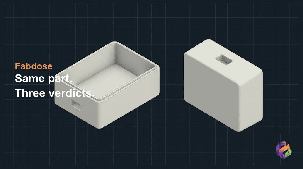
The part below is a small sensor housing, and its +X outer side wall is a single face of 786.5 square mm with 2 degrees of taper modelled into it. Nothing about that face changes across the three runs. What changes is which way the file is standing when the check reads it.
| Run | How the file is oriented | What that face reports |
|---|---|---|
| A | as designed, cavity opening facing up | draft angle 2.0, clears the 2.0 minimum |
| B | rotated 90 degrees, connector wall facing up | draft angle 0.0, insufficient draft |
| C | flipped 180 degrees, exported upside down | draft angle -2.0, classified as an undercut |
Same face, same taper, same file. The tooling estimate across the three runs goes from $14,000 to $62,000 to $90,000. Those are the tool's built-in static estimates and not factory quotes, but the direction is the point: the orientation you export in is not a formatting detail, it is the question you are asking.
Which way should the mold open on this part?
Along the axis the hollow has to open toward, which on a housing is the axis the core withdraws along. Then you confirm it instead of assuming it, by running the file in each candidate orientation and reading which one leaves the fewest features fighting the pull.
That confirmation step is easy to skip, because a parting-line decision feels like something the molder makes later. It is not. By the time the molder sees the file, the draft is already modelled in one direction, and that direction is a decision somebody made, often by accident, when they picked a sketch plane.
The part below is a synthetic, representative model built for this post, not a real customer file. It is a sensor housing, 60 by 40 by 20mm in ABS with a 2.0mm nominal wall, modelled as an open-top box: 2mm floor, walls drafted 2 degrees per side, four screw bosses standing on the inner floor with blind cored holes, and a 12 by 6mm connector opening cut through one side wall. Thirty-five faces in total. Every run used the same command:
python cli.py analyze <part>.step ABS --process injection_molding --wall-thickness 2.0
The only difference between the three files is a rotation applied to the solid before export.
What does the report say when the file is oriented as designed?
Run A returns 7 located findings: 1 undercut and 6 draft violations. The tooling estimate lands at $14,000, on the moderate tier, with a single slide core line item. (Located findings, throughout this post, means findings that carry a face ID and a coordinate. Each run also returns one wall-thickness item, which carries neither and is covered at the end.)
The one undercut is face 8, 13.1 square mm, at (0.00, 18.97, 14.00) in the file's own coordinates. Verbatim:
Critical undercut, requires complete redesign or advanced mold technique
detected at face 8 (angle: 90.0°)
That face is the roof of the connector opening. It points straight back against the pull, which is why the reported magnitude is 90.0, the maximum on this scale: 0 means the face is parallel to the pull, and 90 means it faces directly away from it. The two side walls of the same opening, faces 7 and 9 at 7.8 square mm each, come back separately as Draft angle 0.0° at face 7 is below minimum 2.0°. So the whole connector opening costs three findings and, in the cost estimate, one slide core at $4,000.
The remaining four draft findings are the cored holes in the bosses, faces 27 through 30 at 56.8 square mm each, drafted 1.0 degree against a 2.0 degree minimum. That threshold belongs to the tool, not to your molder. Commonly cited tables for ABS put the minimum near 1 degree and the recommendation at 1.5 to 2 degrees on a smooth surface, so a 1 degree hole sits right on the floor and is a conversation rather than a defect. The report gives you the measured angle so you can have that conversation with a number in hand.
Everything else clears. The outer walls report 2.0. The inner floor, face 18 at 1902.9 square mm, reports 90.0 and is clean, because a face pointing straight along the pull direction is as drafted as a face can be. The outer base, face 0 at 2400 square mm, is marked is_parting_surface: true and exempted.
What changes when the file is rotated 90 degrees?
Run B returns 30 located findings: 3 undercuts and 27 draft violations. The complexity in the cost summary moves from moderate to complex, the base tooling estimate from $10,000 to $50,000, and the total to $62,000 with three slide core lines.
The rotation was chosen for a reason a designer would actually give: it points the connector opening at the sky, so the opening stops being an undercut. And it works. The face that was the only critical finding in run A is gone from the list.
What arrives instead:
| Face | Area (mm²) | Run A | Run B |
|---|---|---|---|
| 14 | 936.6 | draft 2.0, clear | undercut, angle 88.0 |
| 13 | 8.9 | draft 2.0, clear | undercut, angle 45.0 |
| 15 | 8.9 | draft 2.0, clear | undercut, angle 45.0 |
| 2 | 786.5 | draft 2.0, clear | draft 0.0, below minimum |
| 0 | 2400.0 | parting surface, exempt | draft 0.0, below minimum |
Face 14 is the inner cavity wall on the connector side. In run A it is a properly drafted wall that lets the core withdraw. In run B it is a 936.6 square mm surface facing 88 degrees away from the new pull, which is to say the core can no longer come out at all. Faces 13 and 15 are the small corner blends at the top of the box, 8.9 square mm each, and they flip the same way for the same reason.
The 27 draft findings are the rest of the housing. Every wall that was tapered along the old pull is now standing parallel to the new one, so it reads 0.0. That includes the part's own base, face 0, which was the parting surface a moment ago.
This is the trade in plain numbers. Run B removes one 13.1 square mm undercut and creates three, one of which is 936.6 square mm. It also turns a part where six faces needed a draft conversation into a part where twenty-seven do.
What happens if the file is simply exported upside down?
Run C returns 32 located findings: 30 undercuts and 2 draft violations, with ten slide core lines and a $90,000 tooling estimate. This is the run nobody chooses on purpose, and it is the one most likely to happen by accident.
Ten of those undercuts are reported at the full 90.0 magnitude: face 18, the inner floor at 1902.9 square mm; face 6, the floor of the connector opening; faces 23 through 26, the boss top faces; and faces 31 through 34, the bottoms of their cored holes. The other twenty are reported as Minor undercut, may not require action detected at face 1 (angle: 2.0°) and similar. Sixteen of them come in at exactly 2.0 degrees, which is every outer wall, inner cavity wall, corner blend and boss flank that carried 2 degrees of draft a moment ago. The remaining four are the cored holes at 1.0.
Read that group carefully, because it is the whole lesson in one line. Sixteen faces that were correctly drafted are now, at exactly the same 2 degrees, undercuts. The cost model attached its slide core lines only to the ten critical ones, which is why the estimate is $50,000 plus ten lines rather than thirty.
A part exported upside down does not look wrong on screen. It looks like the part. The report is the thing that notices.
Why does rotating the file change the answer at all?
Because a draft angle is not a property of a face. It is the angle between a face and the direction the mold opens, and this check reads that direction as the file's own +Z axis.
That is worth stating plainly rather than burying, because it decides how you use the tool. The check does not guess your parting line and it does not search orientations for you. It answers one question exactly: given that the mold opens along the direction this file is standing in, which faces fight it. Orient the file the way the tool will open, and the answer is about your part. Orient it any other way, and the answer is about a mold nobody is going to build.
The upside of the same fact is that it makes a parting-line hypothesis cheap to test. Rotating a solid and exporting a second STEP file is a couple of clicks in any CAD tool, and it turns "I think it should open this way" into two lists of face IDs you can compare. That is what runs A, B, and C are.
If the terms here are unfamiliar, the definitions of draft and undercut are worth reading first.
So which orientation should this housing use, and what happens to the connector opening?
Run A, and the connector opening gets solved as a feature rather than as a reason to rotate the tool.
The decision rule that falls out of these three runs is not subtle: the pull direction is set by the bulk of the geometry, not by the one feature that is inconvenient. Twenty-seven walls and a floor were drafted for one axis. One 13.1 square mm face was not. Rotating the mold to please that one face costs three undercuts, twenty-seven draft findings, and a tooling tier.
So the opening stays where it is, and it gets one of the ordinary fixes for a through opening in a side wall. Bypass shut-off steel, where the core and cavity touch through the opening, is the usual first candidate for a hole that goes all the way through, and a side-action slide is the fallback the cost model assumes when it adds its $4,000 line. Which of those applies is a question for the molder, and the difference between them is real money. The six standard ways to remove an undercut are the menu to bring to that conversation. What the report gives you is the face ID and the coordinate to point at while you have it.
What does this comparison not tell you?
It does not tell you what the tool will actually cost. The dollar figures above are the tool's built-in static estimates keyed to a complexity tier and an undercut count, not quotes, and a molder's number will differ.
It does not pick the parting line for you. It evaluates the one your file implies. On a part with two genuinely competitive orientations you still have to run both and read the comparison yourself, which is exactly the workflow this post is about.
It does not locate flow-dependent defects, and it does not claim to. All three runs also returned risk flags for sink marks, weld lines, air traps, jetting and similar. None of those carry a structured face ID or coordinate, because they depend on gate placement, cooling and melt behaviour rather than on geometry alone. They are a molder's DFM review or a flow simulation, not a geometry check.
And it is not a wall-thickness study. Each of the three runs also returns a single wall-thickness item. It is not a located finding, since it carries no face ID and no coordinate, and it is outside what a pull-direction comparison can say anything about. If wall thickness is your question, that is a separate conversation with a molder, not a number to read off these three runs.
What is the takeaway?
Before you read a manufacturability report, check which way the part is standing in the file. The report is answering for that direction and no other. Three orientations of one unchanged solid produced 7, 30 and 32 located findings here, and every one of those reads is correct for the mold it describes.
Fabdose reads your STEP or STP file on your own computer, on Windows or Mac, and locates face by face which walls fall below the draft threshold and which features create undercuts, before the file goes to anyone who quotes it. Your CAD geometry is processed on your computer; the defect findings and their written explanations are processed by AI. It covers the geometry-only problems, undercuts and draft, and it does not simulate the flow-dependent defects that need a molder's review.
If you have a housing about to go out for a quote, export it twice, once in each orientation you are considering, and read the two lists side by side. It is a cheap way to test a parting-line hypothesis before you commit to one.
Check your design with Fabdose
FAQ
Which way should an injection mold open on my part?
Along the axis the hollow has to open toward, which on a housing is the axis the core withdraws along. Confirm it rather than assume it: export the same solid in each candidate orientation and compare the counts. On the housing here, opening along the axis the box was drafted for produced 1 undercut and 6 draft findings. Rotating 90 degrees to free the connector opening produced 3 undercuts and 27 draft findings and moved the tooling tier from moderate to complex.
Does the orientation of my STEP file change the DFM result?
Yes, completely. Fabdose evaluates the pull direction as the file's own +Z axis, so the way the solid sits in the file is the mold-opening direction the report answers for. The three runs above are the same solid, rotated, and they return 7, 30 and 32 located findings.
Why does a face with 2 degrees of draft come back as a 2 degree undercut?
Because draft is signed, and the sign is measured against the pull. The 786.5 square mm side wall reports 2.0 pulled one way, 0.0 pulled at 90 degrees to that, and -2.0 pulled from the opposite end, where it is classified as an undercut. The taper that releases the part in one direction locks it in the other.
Should I rotate the part to get rid of an undercut?
Only if the rotation removes more than it creates, which on a drafted housing it usually does not. Here, rotating to free a 13.1 square mm connector roof turned a 936.6 square mm cavity wall into an 88 degree undercut and every drafted outer wall into a zero-draft finding.
What is the difference between a located finding and a risk flag?
A located finding carries a face ID, an angle, and an X, Y, Z position. Undercuts and insufficient draft are geometry-only, so they are located. Weld lines, sink marks, jetting and flow-front air traps depend on melt flow and cooling, so they appear as risk flags with no structured face ID or coordinate, and belong to a molder's DFM review or a flow simulation.
Fabdose is a desktop tool for checking STEP and STP files against injection molding design rules on Windows and Mac. It locates draft violations and undercuts face by face, before the file goes out for a quote. Your CAD geometry is processed on your own computer; defect findings and descriptions are processed by AI. The three runs above are real, unmodified engine runs against a synthetic representative housing built for this post; the dollar figures are the tool's built-in static estimates, not factory quotes.