Sending a CAD file to a factory without knowing whether it can be manufactured is one of the most expensive mistakes in product development. The quote comes back with a list of issues, or it does not come back at all. Either way, you are now weeks behind and facing a redesign with tight timeline pressure.
The question every product designer should be able to answer before sending a file is: can this geometry actually be made with the process I have in mind, at the tolerance I need, without the factory having to rework or reject it?
That answer is not always obvious, and the ways most designers check today all have real gaps.
What does "manufacturable" mean for a CAD design?
Manufacturability is a CAD design's compatibility with a specific manufacturing process — meaning its geometry satisfies the dimensional and shape constraints that process requires. A part is manufacturable when it can be produced at the intended volume and tolerance without redesign, tooling rework, or excessive manual intervention. The same geometry may be manufacturable by CNC machining but not injection molding, because each process imposes a different set of constraints.
How to check if your design is manufacturable: step-by-step
Checking your design for manufacturability before sending it to a shop takes four steps.
- Choose the target process. Manufacturability is always relative to a process — injection molding, CNC, die casting, or 3D printing. Each has different wall thickness minimums, draft requirements, and geometric constraints. Decide which process you are targeting before checking.
- Run a geometry analysis on the STEP file. Load your STEP or STP file into a tool that can open the file and compute geometric properties — not a language model that reads the file as text, but software with a geometry kernel that can measure wall thickness, face normals, and surface topology.
- Review the flagged issues by severity. A useful analysis ranks findings: which issues will cause manufacturing failure, which will affect cost or quality, and which are minor. Address the high-severity items first.
- Iterate and re-run before sending for quotes. The goal is to arrive at the factory or the DFM consultant with a part that has already been through a first filter — so the external feedback focuses on judgment-level decisions, not geometry basics.
What "manufacturable" actually means for a physical part
Manufacturability is not a single property. It is a combination of geometry properties that interact with a specific manufacturing process. A part that machines perfectly in CNC may be completely impossible to injection-mold. A part designed for die casting may have features that require expensive hand-finishing if made by SLA printing.
The key geometric properties that determine whether a part is manufacturable depend on the process, but the common ones are:
Wall thickness. Every process has a minimum wall thickness below which material either will not flow (injection molding, die casting), will crack under machining forces (CNC), or will be too fragile to handle (SLA). For injection molding in standard ABS, the practical minimum is around 1.2 mm. Walls below that threshold risk incomplete fill, sink marks, or warpage.
Draft angles. Parts that are pulled from a mold -- injection molding and die casting especially -- need tapered faces so the part can release without tearing. The standard rule is 1 to 3 degrees of draft per side. Vertical faces with zero draft will stick to the mold and either tear the part or damage tooling.
Undercuts. An undercut is any feature that is trapped by the mold geometry in the pull direction. A snap-fit tab on the inside of a housing, a side hole perpendicular to the pull direction, a recessed groove -- these all require side-actions or collapsible cores, which add tooling cost and complexity. If you have undercuts you did not design intentionally, you need to know about them early.
Tolerances relative to the process. CNC machining can hold tolerances down to a few microns on a good day. Injection molding typically holds +/- 0.1 to 0.3 mm depending on part size and material. If your design has a tight-tolerance fit that only works within +/- 0.05 mm, and you are quoting injection molding, you have a mismatch that will only surface when you receive parts.
Process fit in general. Beyond the individual checks, the overall geometry needs to match what the process is good at. Deep pockets with very high aspect ratios are expensive or impossible in some CNC setups. Thin features that extend far from the base are risky in injection molding due to differential cooling. Long, thin pins or shafts in die casting may not fill completely.
Insight
The most common source of late-stage redesign is not a single catastrophic issue -- it is a set of smaller geometry mismatches that each individually seem minor, but together make the part difficult to quote, expensive to tool, or unreliable in production.
How designers check today, and why each has a gap
Ask the factory
The obvious approach: send the file, ask what they think, get a quote with feedback.
The problem is that most factories will not do free design feedback before a quote, and even when they do, their incentive is to get your business, not to be thorough about problems that would push work back to you. A factory quoting on a part with manageable issues may simply price in the extra work and ship you parts that have consistent sink marks.
If you send the same part to three factories, you may get three different feedback sheets, none of them complete. And you have now spent two to three weeks waiting.
Hire a DFM consultant or have an engineer review it
Accurate. A good manufacturing engineer who looks at your STEP file will catch real issues and explain the root cause. They can tell you which process fits the part and why, and give you concrete changes to make.
The gap here is speed and cost. A proper DFM review from a consultant or contract engineer takes days to schedule, costs several hundred to a few thousand dollars depending on part complexity, and is hard to justify early in an iteration cycle when the design is still changing.
You end up either skipping it to save budget, or doing it once at the end when it is most expensive to act on the findings.
Ask ChatGPT or Claude
AI assistants know DFM rules. Ask about draft angles and you will get a reasonable answer covering typical ranges for injection molding. Ask about minimum wall thickness for CNC in aluminum and you will get a defensible rule of thumb.
The gap is that AI language models cannot see your actual geometry. When you paste a STEP file into ChatGPT or Claude, what it receives is text -- AP203 or AP214 entity definitions. The model has no way to reconstruct the 3D shape from those definitions, estimate wall thickness from the part's shell geometry, detect which faces have insufficient draft, or identify undercut features relative to a pull direction.
You get a response that sounds DFM-aware but is not grounded in your actual part. You might get a response that says "looks reasonable" when your part has six locations with 0.4 mm walls. The model cannot measure anything from the file because it never rebuilt the geometry.
This matters most when you have already done the design work and need a specific answer about this part, not a general education about DFM rules.
Warning
Using an AI chat tool to review your STEP file for manufacturability feels like a check, but it is not. A confident-sounding response about a file the model cannot parse is false assurance at the worst time in your cycle.
What a fast first-pass geometry check looks like
A useful first-pass check is one that runs on your actual geometry, covers the key failure modes for the processes you are considering, and gives you specific findings rather than general advice.
That means software that loads the STEP file, builds a geometric representation of the part, and then computes: where the wall thickness falls below the process threshold, which faces lack adequate draft relative to a pull direction, where undercuts are located, and how the overall shape fits the process constraints. The output should be specific -- per-face, per-feature, with severity ranked so you know what to fix first.
This kind of check does not replace a manufacturing engineer. It is a self-check step you can run before the part leaves your desk. The goal is to find the obvious geometry issues early, while changing them is cheap and does not require coordination with anyone.
Where it fits in the workflow: after you finish a design iteration and before you send it for quoting, DFM review, or internal sign-off. Not as a gate, but as a sanity check that catches the issues you did not catch during modeling.
A note on cost estimates by process
One thing that is useful alongside a geometry check is a rough cost signal by process. If your part has geometry that works for both CNC and injection molding, knowing that the tooling amortized cost for injection molding at your expected volume is roughly 40 percent lower than CNC unit cost changes which direction you take the design.
This is not a supplier quote. It is an order-of-magnitude signal that helps you make better design decisions earlier, before you have a tooling vendor or a volume commitment. The accuracy depends on part complexity and region, but even a rough range is more useful than no signal at all.
Trying a first-pass self-check
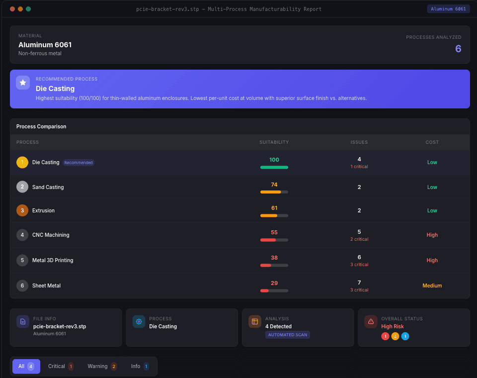
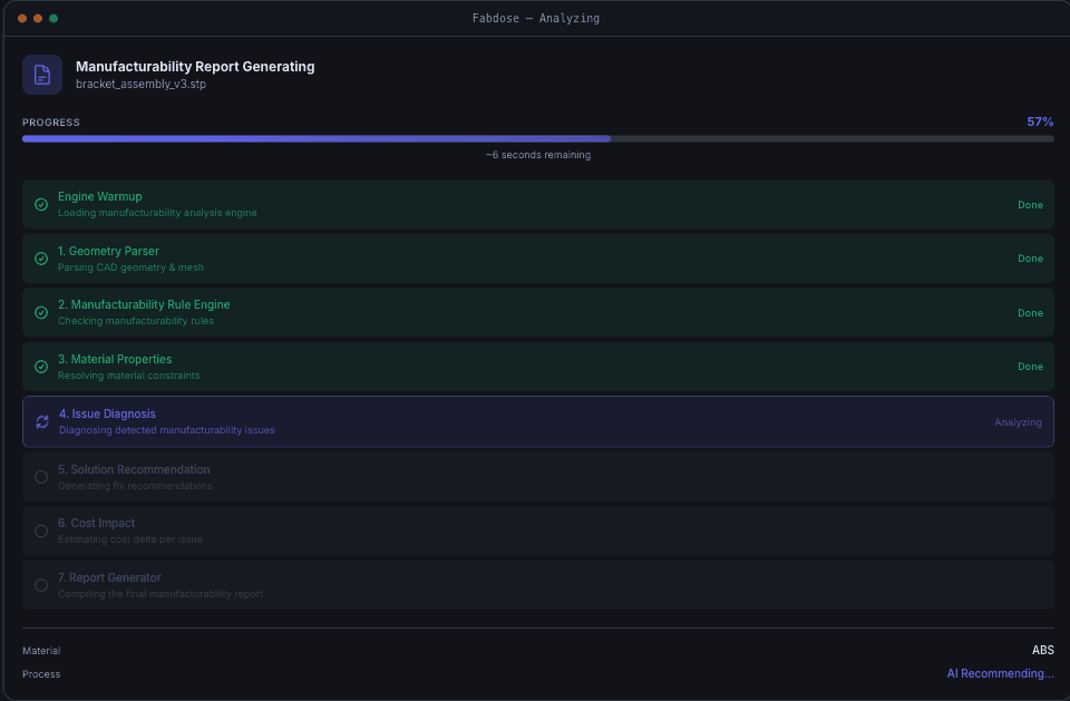
Fabdose is a local-first DFM analysis app for product designers on Mac. You give it a STEP or STP file and in roughly one to three minutes it runs geometry checks for the process you pick -- injection molding, CNC, die casting, or SLA/3D printing. It flags draft issues, undercuts, and process-fit problems -- severity ranked, with a 3D viewer that pins those issues on the actual geometry. Wall thickness gets a part-wide read too: a variation-based warp-risk flag, not a face-by-face pin -- it's a nominal estimate, not a full shell analysis. It also gives a cost-range estimate per process as a rough planning signal. The free tier covers one process per analysis; the auto-comparison that runs your part across all four processes at once is a Pro feature.
Your CAD files are never uploaded — the file stays on your computer throughout. The defect findings are processed by AI and synced to your account.
It is not a replacement for a manufacturing engineer or factory DFM review. It is the step before those -- a way to find the obvious geometry issues yourself, fix them, and arrive at the factory or the engineer with a cleaner part.
The free tier includes five analyses, with an account required (Google or email) and no credit card needed.
Frequently asked questions
What are the most common reasons a CAD design fails manufacturability review?
The most common failures are insufficient draft angles on molded parts (faces parallel to the pull direction that will tear on ejection), wall sections below the minimum thickness for the process (typically under 1.2 mm for injection molding in ABS), and undercuts that require additional tooling to address. These three issues appear in the majority of first-pass DFM rejections because they are easy to miss during the design phase.
Can I check manufacturability without sending my file to a factory or consultant?
Yes. Geometry-analysis software can check your STEP file against process constraints locally — measuring wall thickness, detecting undercuts, evaluating draft angles — without requiring a human reviewer or factory quote. This type of first-pass check is not a substitute for expert review, but it catches rule-based geometry issues you can fix before involving anyone else.
How long does a first-pass manufacturability check take?
A local geometry analysis of a typical STEP file runs in one to three minutes on a modern laptop. A factory DFM review attached to a quote request takes two to five business days. A DFM consultant engagement takes days to schedule and complete. The difference in timing is why a first-pass check is worth running on every design iteration.
What file format do I need for a manufacturability check?
STEP (Standard for the Exchange of Product model data) files — with extensions .step or .stp — are the standard neutral format that geometry-analysis tools work with. Most CAD applications can export to STEP directly. SolidWorks, Fusion 360, Rhino, and Onshape all support STEP export.
Does a manufacturability check replace a manufacturing engineer?
No. A geometry-based check flags rule violations — wall thickness under threshold, draft angle insufficient, undercut present. It does not apply material-specific judgment, regional tooling knowledge, or production volume context the way an experienced manufacturing engineer does. The right model is: run the geometry check yourself first, then bring a cleaner part to the engineer so their time focuses on decisions that require judgment.
Check your STEP file on your Mac before it reaches the factory. Five analyses free, no credit card.
Download Fabdose Free